RF Switch Basics
RF and microwave switches transmit signals efficiently over the transmission path. The function of such a switch can be characterized by four basic electrical parameters.
Although multiple parameters are related to the performance of RF and microwave switches, the following four are considered critical parameters due to their strong correlation: isolation, insertion loss, switching time, power handling capability.
Isolation, the attenuation between the input and output of a circuit, is an indicator of the effectiveness of a switch’s cutoff. Insertion loss (also known as transmission loss) is the total power lost when the switch is in the on the state. Since the insertion loss directly leads to an increase in the system noise figure, insertion loss is the most critical parameter for the designer.
The switching time is the time required for the switch to transition from the “on” state to the “off” state and from the “off” state to the “on” state. This time can reach the micro-second level of the high-power switch, down to the nanosecond level of the low-power high-speed switch. The most common definition of switching time is the time from the input control voltage reaching 50% to the final RF output power reaching 90%. In addition, power handling capability is defined as the maximum RF input power that a switch can withstand without any permanent electrical degradation.
RF and microwave switches can be divided into two categories: electromechanical relay switches and solid state switches. These switches can be designed in a variety of different configurations – from single-pole single-throw to single-pole, six-throw, or more-throw configurations that convert a single input to 16 different output states. The diverter switch is a double-pole-double-throw configuration switch. This type of switch has four ports and two possible switch states to switch the load between the two sources.
Electromechanical relay switches have low insertion loss (<0.1db), high isolation (>85dB), and can switch signals at millisecond speeds. The main advantage of this type of switch is that it operates over the DC to millimeter wave (>50 GHz) frequency range and is not sensitive to electrostatic discharge. In addition, electromechanical relay switches handle higher power levels (up to several kilowatts of peak power) without video leakage.
However, in the operation of electromechanical RF switches, there are some issues that deserve our attention. The standard life of such switches is only about 100 times, and their components are sensitive to vibration. Service life is the total number of switches that an electromechanical switch can perform to meet RF and repeatability requirements. High quality or high-reliability electromechanical switches are suitable for applications requiring long life. The reliability and other properties of these switches are extremely superior and have a service life of up to 1000 cycles. The longer service life described above results from a more robust actuator and a drive linkage that is more optimized in terms of magnetic efficiency and mechanical rigidity. In addition, these switches are designed to withstand harsher environmental conditions and meet MIL-STD-2002 standards for sinusoidal and random vibration and mechanical shock requirements.
For example, Pasternack offers a standard electromechanical RF switch with a lifetime of 1 million cycles and a reliable electromechanical RF switch with a lifetime of 2 to 10 million cycles. The company’s PE71S6064 single-pole double-throw reliability switch is one of the above products, its operating frequency range is DC ~ 40GHz, and the service life is guaranteed 10 million times.
In contrast, since the circuit assembly of a solid-state RF switch is relatively flat and does not contain large components, its package thickness is small and the physical size is usually smaller than that of an electromechanical switch. The switching elements used in solid-state RF switches are high-speed silicon PIN diodes or field effect transistors (FETs), or integrated silicon or FET monolithic microwave integrated circuits. These switching elements are discretely integrated on the same board with other chip components such as capacitors, inductors, and resistors.
Switch products that use PIN diode circuits have higher power handling capabilities, while FET type switch products typically have faster-switching speeds. Of course, since the solid-state switch contains moving parts, its service life is unlimited. In addition, the solid state switch has high isolation (60~>80dB), and the switching speed is extremely fast (<<100 nanoseconds), and the circuit has better impact/vibration resistance.
Other notable features of solid-state RF switches include their insertion loss. Solid state RF switches are inferior to electromechanical switches in terms of insertion loss. In addition, solid state RF switches have limitations in low-frequency applications. This is because the lower limit of its operating frequency can only be up to kilohertz instead of DC. This limitation stems from the carrier lifetime characteristics inherent in the semiconductor diodes used. In addition, solid state RF switches are more sensitive to electrostatic discharge and their power handling capabilities depend on the switch configuration, connector type, operating frequency, and ambient temperature. Some configurations of PIN diode switches can handle peaks of several kilowatts of power but at the expense of lower switching speeds. An example of a PIN diode switch is Pasternack’s PE7167 single-pole, four-throw switch. The product operates from 500MHz to 40GHz, with a maximum switching speed of 100 nanoseconds and an input power handling capability of up to +20dBm.
Overall, solid-state RF switches are more reliable, longer lasting, and faster switching than electromechanical switches. Therefore, in applications where higher switching speeds and reliability are required, solid-state RF switches should be preferred; in applications requiring wide frequency band coverage down to DC and low insertion loss, electromechanical switches are preferred; For applications that are absolutely required, high-reliability switches are preferred.
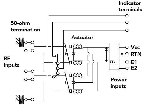
As shown in the above diagram, Pasternack’s PE71S6064 single-pole-double-throw switch uses several typical components of electromechanical RF switches, including DC 28V latching actuators, several independent contacts that connect switch status indicators, and those located in idle ports. 50 ohm termination matching resistor
Designers should be aware of other features of the various switch products described above, such as a 50 ohm resistive load. In the switching circuit, any unused open transmission line may resonate at a frequency within the microwave range. This resonance can reflect electrical energy back to the RF source under working conditions, thereby damaging it. For systems operating at 26 GHz or higher, the above damage will be more severe due to the greatly reduced isolation. Therefore, most transmission lines are designed with a 50 ohm impedance, so that the RF switch has very little reflected energy after the built-in 50 ohm resistive load.
Electromechanical RF switches are classified into two types: terminated and non-terminated. In a terminating switch, when all channels are terminated with a 50 ohm load, the selected channel is turned off, thereby blocking or isolating all currents. As such, the energy of the incident signal will be absorbed by the termination resistor and not reflected back to the RF source. A 50 ohm load is placed in the non-terminated switch, so impedance matching to reduce energy reflection must be achieved by other parts of the system. The advantage of a non-terminated switch is its low insertion loss.
Another important feature of electromechanical RF switches is their armature relay mechanism. When the coil is energized, the induced magnetic field will cause the armature coil to move, opening or closing the contact. The non-latching switch is provided with a spring or a magnet, which can maintain the switch in an initial normally closed state when the current does not flow. This type of switch is suitable for applications where the switch must be restored to a known state when the power supply is interrupted.
There is a latching mechanism in the latching switch and there is no default position, so it remains in the last state before the power is turned off. Since the contact coil of the latching relay switch consumes power only at the moment the relay is turned off, it is suitable for applications where power dissipation is a problem.
In addition, some other types of switches have a fail-safe mode of operation. In this mode, once the voltage applied to the coil disappears, the RF channel returns to the power-off state. However, since this mode keeps the power on only when a voltage is continuously applied to the coil, the average time between failures of the switch using this mode is shorter than that of the lock switch.
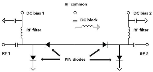
The figure shows an example of a single-pole-double-throw RF switch that uses a PIN diode as a switching element and as a passive device that blocks the RF channel from the DC bias signal path. In a typical application, the common RF terminal shown can be connected to the system antenna, while the RF terminals 1 and 2 are connected to the transmitter and receiver, respectively. The PIN diode acts as a radio frequency resistor whose resistance is regulated by the forward DC bias current of the diode. In general, for a typical PIN diode, the dc bias current can adjust its RF resistance value over three or more orders of magnitude. When the diode is in an off-cut state, its impedance is high enough to approach the impedance of the circuit breaker.
Another notable feature of electromechanical RF switches is a set of auxiliary DC contacts that are connected to the RF channel switching coil. Normally, these auxiliary contacts are used to control the indicator light or signal light to indicate the status of the RF channel. In addition, these contacts can also be used to provide status information to external control systems.
Switch details
Solid-state RF switches are available in both absorbing and reflective versions. The snubber switch has a 50 ohm termination matching resistor at each of its output ports to achieve a lower voltage standing wave ratio (VSWR) in both states. The terminating resistor provided on the above output port can absorb the incident signal energy, and the port not connected to the terminal matching resistor will reflect the signal. When the input signal must propagate through the switch and become obsolete, the open port is disconnected from the termination matching resistor, allowing the energy of the signal to propagate completely from the switch. Absorption switches are ideal for applications where the echo reflection from the RF source is minimized.
In contrast, there is no termination resistor in the reflective switch to achieve the purpose of reducing the insertion loss of the open port. Reflective switches are suitable for applications that are not sensitive to high voltage standing wave ratios outside the port. Further, in the reflective switch, impedance matching is achieved by components other than the port.
Another important feature of the solid state switch is its drive circuit. Some types of solid state switches incorporate input control voltage drivers whose input control voltage logic states enable specific control functions – providing the necessary current to ensure that the diode can obtain a reverse or forward bias voltage.
Electromechanical and solid-state RF switches are available in a variety of products with different package sizes and connector types – most coaxial switch products operating up to 26 GHz use SMA connectors; up to 40 GHz use 2.92 mm or K connectors; use a 2.4mm connector up to 50GHz; use a 1.85mm connector up to 65GHz.
Switches with waveguide ports have the lowest insertion loss and are therefore widely used for high power communication signals in the microwave and millimeter wave bands. Coaxial switch products with large N-type or TNC connectors have higher power handling capability (can handle up to hundreds of watts of continuous wave power). In addition, products for different applications can be packaged in different packages – from “commercial grade” packages that are never isolated from the environment to tightly sealed “highly reliable” packages that withstand harsh environmental conditions.
From:http://www.hj-antenna.com/


Leave a Reply
Want to join the discussion?Feel free to contribute!