Application of ZVL Network Analyser in Radio Frequency Product Measurement
In the research and development and production process of RF products, it is often necessary to perform spectrum analysis of RF signals, demodulation analysis of signals, reception sensitivity test and S-parameter test of hardware circuits. Engineers use this to optimize and verify the design of products, so that the products The performance is in an optimal state; in order to ensure that the electromagnetic compatibility design of the product meets the specifications, it is also necessary to perform an electromagnetic compatibility test, that is, a pre-certification test. Therefore, spectrum analyzers, vector network analyzers, measurement receivers, noise figure analyzers and signal analyzers are indispensable. For units developing ordinary RF products, very expensive test instrument investment is difficult to recover in a short time. The ZVL, a measuring instrument that combines the above measurement functions with Rohde & Schwarz, is cost-effective and can solve this problem well.
ZVL application example
Board diagnostics
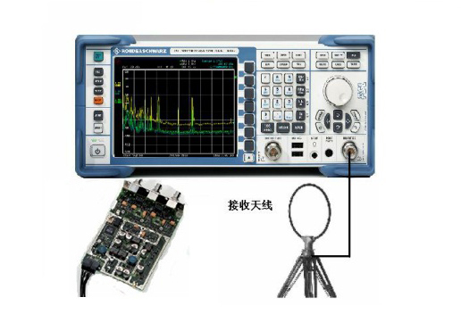
Between different modules of a circuit board and between different circuit boards in a system, because the wiring of the clock signal lines is unreasonable, interference often occurs with each other, resulting in instability and performance degradation of the entire system. For example, the sensitivity of the GPS receiver is very high. The spurious signals of the circuit board and the harmonics of the clock signal may fall in the working frequency band of the GPS. This interference signal will enter the GPS receiver through the antenna and affect the sensitivity. The antenna is placed at different positions. The degree of impact on sensitivity is still different. Therefore, board diagnostics are very important for RF product performance optimization. As shown in the figure below, the ZVL is used as a spectrum analyzer. The RF input port is equipped with Rohde & Schwarz probes HZ-15 and HZ-16. It can clearly locate the strong spurious signals from which areas of the board. Even which chip is pinned.
2. Analog modulation signal demodulation analysis
For analog modulated signals such as AM, FM, and Phim, it is often necessary to analyze their modulation characteristics. For example, wireless FM walkie-talkie has strict requirements on its transmission center frequency and modulation frequency offset. The center frequency is not allowed to cause the sensitivity of the receiver to decrease, the transmission distance is shortened; the modulation frequency offset is too small, the modulation index becomes smaller, and the signal-to-noise ratio of the receiver decreases. The modulation frequency offset is too large, the signal-to-noise ratio of the receiver is guaranteed, but the adjacent channel signal will be interfered, so that crosstalk will occur; the transmission power is too large, the battery consumption is large, the standby time and working time are shortened, and other radios are The device caused some interference. The transmission power is too small and the transmission distance is limited. Therefore, the measurement of the modulation frequency, modulation frequency offset, carrier frequency and power of the FM signal is very important. As shown in the figure below, the signal analysis function of ZVL is displayed to measure the demodulation result of the FM FM signal, and the upper part shows the relationship of the modulation signal to time.
From:http://www.hj-antenna.com/


Leave a Reply
Want to join the discussion?Feel free to contribute!